OhmPediaPassive Components and LawsCapacitance
Capacitance
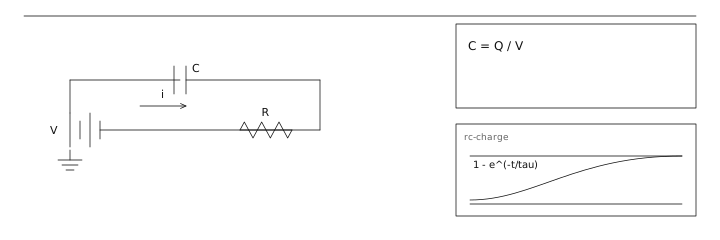
电容 C = Q / V
- Symbol
- C = Q / V
- Unit
- farads (F) · Q in coulombs · V in volts · ε in F/m
- Section
- Passive Components and Laws
- Published
- 2026-08-21
- Author
Capacitance is the ratio of stored charge to voltage, C = Q / V. Because charge cannot move instantly, the voltage across a capacitor cannot change instantly either, which makes it a short-term energy store and the fundamental component of nearly every filter and timing circuit.
The ability of two insulated conductors to store charge, one coulomb per volt.
Geometry and the dielectric
For a parallel-plate capacitor, C = ε_r ε₀ A / d. ε₀ is 8.854 × 10⁻¹² F/m; the dielectric constant ε_r is 1.0 for air, about 2.2 for PTFE, 3.9 for silicon dioxide, and 1000–3000 for the barium-titanate ceramic in a high-capacity X7R or Y5V chip. Using ε_r to pack more capacitance into a small volume also raises the dielectric losses and makes the value sensitive to voltage and temperature — that trade is the whole story of ceramic capacitors.
Capacitor families at a glance
The intended application decides the family long before the capacitance does.
| Type | Typical range | Strengths | Weaknesses |
|---|---|---|---|
| C0G / NP0 ceramic | 0.5 pF – 0.1 µF | ±30 ppm/°C, no voltage coefficient, very low loss | Large and expensive above 10 nF |
| X7R ceramic | 1 nF – 22 µF | Compact, ±15 % over −55…125 °C | Value drops 20–50 % under DC bias |
| Aluminium electrolytic | 1 µF – 100 mF | High capacitance per volume, cheap | ESR rises below 0 °C, lifetime halves per 10 K rise |
| Film (polypropylene) | 1 nF – 100 µF | Low loss, self-healing, very stable | Bulkier and costlier than ceramic |
Current, voltage and energy
The defining relation in the time domain is i = C · dv/dt: a capacitor draws current only while its voltage is changing. Energy stored is ½CV², and it is all available — unlike a battery, whose output voltage collapses as it discharges. That is why a capacitor bank can dump hundreds of joules into a fault in microseconds, and why capacitor banks get treated with battery-level caution.
Where the capacitance goes
A capacitor is not a single value in a real circuit. Above self-resonance the parasitic inductance of the package and the leads dominates. In a ceramic chip the effective capacitance falls with applied DC bias and with temperature, so a 10 µF X5R rated 6.3 V operated at 5 V may present only 4–6 µF. Always read the bias curves in the datasheet rather than the headline value.
A 1000 µF capacitor charged to 24 V stores ½ × 0.001 × 24² = 0.288 J. Energising the same capacitor through a 1 kΩ pre-charge resistor means the initial inrush is 24 mA, and the bank reaches 95 % of 24 V in 3 RC = 3 s. Remove the resistor and the inrush is limited only by the supply's own impedance and the ESR, which for a low-ESR electrolytic is a few tens of milliohms — hundreds of amperes for a few hundred microseconds, enough to weld relay contacts.
Adjacent entries
- Impedance 阻抗
Off the shelf
Sources
- Physics LibreTexts https://phys.libretexts.org/Bookshelves/University_Physics/University_Physics_(OpenStax)/University_Physics_II_-_Thermodynamics_Electricity_and_Magnetism_(OpenStax)
- NIST https://www.nist.gov/pml/owm/si-units-electric-current