OhmPediaPower ConversionElectric Power
Electric Power
电功率 P = V · I
- Symbol
- P = V · I
- Unit
- P in watts (W) · V in volts · I in amperes
- Section
- Power Conversion
- Published
- 2026-08-31
- Author
Electric power is the instantaneous rate of energy transfer in a circuit, P = V · I. Combined with Ohm's law it yields two further forms, P = I²R and P = V²/R, which are the ones actually used when checking whether a part will survive.
The rate at which electrical energy is converted, equal to voltage times current.
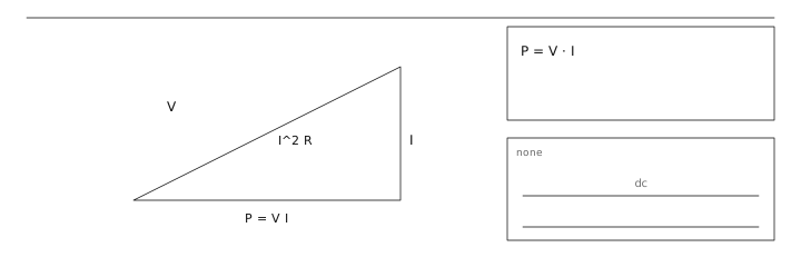
Three forms, three uses
P = V · I is what a power supply delivers. P = I²R is what a resistive part must shed, and it is the form to use when the current is fixed by the rest of the loop. P = V²/R is the form to use when the voltage is fixed — a rail, a bus, a divider tap. Choosing the wrong form is how designers end up with a resistor that is nominally fine but runs at 150 °C.
- P = V · I — sizing a supply or a battery.
- P = I²R — resistor and wiring dissipation when the current is known.
- P = V²/R — dissipation on a fixed rail such as 12 V or 3.3 V.
Average, RMS and real power
For DC the three coincide. For a periodic waveform the instantaneous product p(t) = v(t)·i(t) varies, and the useful quantity is the average over one period. For a purely resistive load that average equals V_rms · I_rms. When the load is reactive, the current and voltage peaks no longer line up, the product overestimates the useful power, and the difference appears as reactive power.
Derating rather than rating
Datasheet power ratings assume a mounting condition that rarely matches the real board. The numbers below are the practical derating a designer should apply before trusting a nominal rating.
| Part | Nominal rating | Practical working limit | Why |
|---|---|---|---|
| 0603 thick-film chip | 0.1 W at 70 °C | ≤ 0.05 W | Rated at 70 °C, derates linearly to 0 W at 155 °C |
| 0.25 W axial metal film | 0.25 W at 70 °C | ≤ 0.15 W | Still air, long leads, no heatsinking |
| SOT-23 transistor | 0.35 W at 25 °C | ≤ 0.12 W | θJA ≈ 250–350 K/W on 2 oz copper |
A 12 V rail feeds an indicator LED string through a 330 Ω resistor. The drop across the resistor is 12 − 2.0 = 10 V, so P = V²/R = 100 / 330 = 303 mW. A standard 0.25 W part is over its rating; a 0.5 W part works, but a better fix is to halve the current by raising the resistor to 680 Ω, which brings dissipation down to 147 mW. The same arithmetic on a 3.3 V rail with a 100 Ω resistor gives only 58 mW, which is why low-voltage rails rarely need derating.
Read first
- Ohm's Law 欧姆定律
Adjacent entries
- Ohm's Law 欧姆定律
- Resistance 电阻
Off the shelf
Sources
- Physics LibreTexts https://phys.libretexts.org/Bookshelves/University_Physics/University_Physics_(OpenStax)/University_Physics_II_-_Thermodynamics_Electricity_and_Magnetism_(OpenStax)
- U.S. Department of Energy https://www.energy.gov/oe/electricity-101
- U.S. Energy Information Administration https://www.eia.gov/energyexplained/electricity/electricity-in-the-us.php