OhmPediaPower ConversionTransformer
Transformer
变压器 V₂ / V₁ = N₂ / N₁
- Symbol
- V₂ / V₁ = N₂ / N₁
- Unit
- turns ratio dimensionless · V in volts · S in volt-amperes (VA)
- Section
- Power Conversion
- Published
- 2026-09-18
- Author
A transformer transfers energy between two windings linked by a common magnetic flux. The voltage ratio equals the turns ratio, the current ratio is its inverse, and the impedance ratio is the square of the turns ratio. It provides galvanic isolation as a by-product of that flux linkage.
Two coupled windings on a shared magnetic core that trade voltage for current.
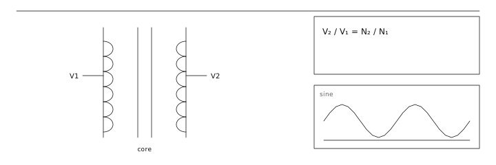
The ratios
With an ideal core, flux links every turn equally, so each turn sees the same volts-per-turn. That single fact produces all three ratios at once: V₂/V₁ = N₂/N₁, I₂/I₁ = N₁/N₂, and Z₂/Z₁ = (N₂/N₁)². A transformer therefore cannot increase power; it only re-packages a fixed volt-ampere product into a more convenient voltage.
- Voltage scales with turns.
- Current scales inversely with turns.
- Impedance scales with turns squared — a 1:2 turns ratio is a 1:4 impedance ratio.
Core, coupling and losses
Real cores lose flux two ways: magnetising current is needed to establish the flux at all, and eddy currents plus hysteresis convert some of it to heat. Laminated silicon steel keeps 50/60 Hz losses tolerable; ferrite is used above roughly 20 kHz where laminations would be too thick. An air core couples poorly but never saturates, which is why it survives in radio-frequency work.
Practical ratings worth reading
A transformer nameplate carries three numbers that matter more than the headline voltage.
| Rating | Meaning | Consequence of ignoring it |
|---|---|---|
| VA (volt-amperes) | Thermal limit of the winding | Winding overheats even if the load is resistive |
| Regulation (%) | V_no-load vs V_full-load | A 15 % part sags 15 % from no-load to full load |
| Isolation class | Withstand voltage of the insulation | Safety failure, not a performance failure |
A mains transformer is specified 230 V to 12 V, 50 VA, regulation 10 %. The turns ratio is 230/12 ≈ 19.2, so the secondary has about one nineteenth of the primary turns. At full 50 VA the secondary current is 50/12 ≈ 4.17 A. Because the regulation is 10 %, the secondary actually sits at 12 V + 10 % ≈ 13.2 V when unloaded, so a downstream 12 V linear regulator must dissipate the extra (13.2 − 12) × 4.17 ≈ 5 W at full load — the reason transformer-fed linear supplies need real heatsinking.
Read first
- Electric Power 电功率
Adjacent entries
- Electric Power 电功率
Off the shelf
Sources
- Physics LibreTexts https://phys.libretexts.org/Bookshelves/University_Physics/University_Physics_(OpenStax)/University_Physics_II_-_Thermodynamics_Electricity_and_Magnetism_(OpenStax)
- U.S. Department of Energy https://www.energy.gov/oe/electricity-101