OhmPediaPower ConversionOhm's Law
Ohm's Law
欧姆定律 V = I · R
- Symbol
- V = I · R
- Unit
- V in volts (V) · I in amperes (A) · R in ohms (Ω)
- Section
- Power Conversion
- Published
- 2026-08-17
- Author
Ohm's law states that the current through a linear resistor is directly proportional to the voltage across it and inversely proportional to its resistance, provided the temperature and the physical dimensions of the element stay constant.
The linear relation between voltage, current and resistance in a resistive element.
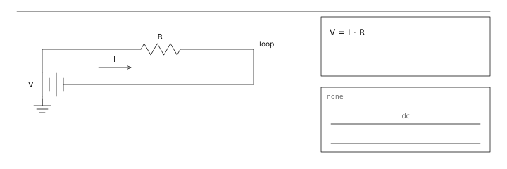
What the law actually constrains
Ohm's law is a statement about a material, not about a circuit topology. It says that the ratio V/I for a given piece of material is a constant over the range of interest. Metals at room temperature satisfy this to within a fraction of a percent; semiconductors, electrolytes and hot filaments do not. Every practical resistor datasheet therefore quotes a temperature coefficient and a maximum working voltage, because both push the element away from the linear region.
Reading it three ways
The same relation rearranged answers three different engineering questions. Which form you reach for depends on which quantity is fixed by the rest of the design.
- V = I · R — find the drop across a known resistor carrying a known current (sizing, level shifting).
- I = V / R — find the current a known source drives into a load (thermal and fuse checks).
- R = V / I — infer an unknown resistance from a measured voltage and current (sensor front ends).
Where it breaks down
The table below lists elements that are routinely mistaken for ohmic. In each case the instantaneous ratio V/I is still defined, but it changes with operating point, so a single number cannot describe the part.
| Element | V–I behaviour | Linear? |
|---|---|---|
| Metal-film resistor, 25 °C | Constant ratio to ±0.1 % over the rated range | Yes |
| Incandescent filament | Resistance rises roughly 8–12× from cold to white heat | No |
| Silicon PN junction | Exponential above about 0.6 V (per University of Mississippi) | No |
| Electrolytic solution | Polarisation, heating and gas evolution shift the ratio | No |
A 9 V supply feeds a 470 Ω resistor. I = 9 / 470 = 19.1 mA and the dissipation is I²R = 172 mW, so a 0.25 W axial part runs at 69 % of rating — acceptable but warm. Drop the same resistor onto 5 V and the current falls to 10.6 mA with only 53 mW dissipated. Doubling the resistance to 940 Ω at 9 V halves the current again to 9.6 mA. Notice that the current tracks the supply linearly, which is exactly what makes this useful for setting bias points.
Adjacent entries
- Resistance 电阻
- Electric Power 电功率
- Kirchhoff's Circuit Laws 基尔霍夫定律
Off the shelf
Sources
- NDT Resource Center https://www.nde-ed.org/Physics/Electricity/ohmslaw.xhtml
- Physics LibreTexts https://phys.libretexts.org/Bookshelves/University_Physics/University_Physics_(OpenStax)/University_Physics_II_-_Thermodynamics_Electricity_and_Magnetism_(OpenStax)
- NIST https://www.nist.gov/pml/owm/si-units-electric-current