OhmPediaSignal and MeasurementLow-Pass Filter
Low-Pass Filter
低通滤波器 f_c = 1 / (2πRC)
- Symbol
- f_c = 1 / (2πRC)
- Unit
- f_c in hertz · R in ohms · C in farads · roll-off in dB/decade
- Section
- Signal and Measurement
- Published
- 2026-09-11
- Author
A low-pass filter passes low frequencies and attenuates high ones, with a transition defined by its cutoff frequency — the point where the output falls 3 dB below the passband. The simplest form is a resistor and a capacitor in a divider, giving a single pole and a 20 dB per decade roll-off for ever after.
A network that passes frequencies below a cutoff and attenuates those above it.
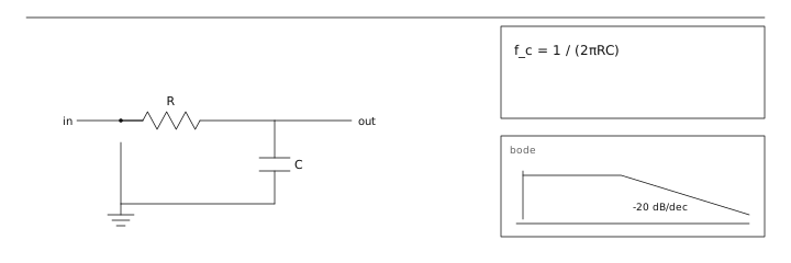
The single-pole response
For an RC low-pass, the transfer function is 1/(1 + jf/f_c) with f_c = 1/(2πRC). At f_c the output is 0.707 of the input and the phase is −45°. One decade above cutoff the output is 0.1 (−20 dB) and the phase is close to −90°. The phase shift matters as much as the amplitude in feedback systems: a single pole can contribute up to 90° of phase lag, and two can contribute 180°, which is enough to turn negative feedback into oscillation.
Order, slope and what it costs
Cascading independent RC sections multiplies the responses, but each section loads the next unless it is buffered, so the simple cascade rarely gives the slope the arithmetic predicts.
| Order | Roll-off | Phase at f_c | Practical form |
|---|---|---|---|
| 1 | 20 dB/decade | −45° | One R and one C |
| 2 | 40 dB/decade | −90° | Buffered RC pair or Sallen-Key |
| 4 | 80 dB/decade | −180° | Two Sallen-Key sections, Butterworth |
| 8 | 160 dB/decade | −360° | Switched-capacitor or DSP |
Butterworth, Chebyshev, Bessel
The classic alignments trade three properties. Butterworth is maximally flat in the passband. Chebyshev allows passband ripple in exchange for a steeper transition. Bessel has the flattest group delay, which means it preserves pulse shapes — the reason it is used on digital signals and in oscilloscope front ends, where overshoot and ringing would corrupt the measurement.
Low-pass filters as anti-aliasing
Before an ADC the low-pass filter must attenuate everything above half the sampling rate, or those frequencies fold back into the band of interest and cannot be removed afterwards. For a 48 kHz audio converter with 24 kHz Nyquist, an input at 25 kHz aliases to 23 kHz — indistinguishable from a real signal. Practical converters use an oversampling modulator plus a digital decimation filter precisely because an analogue filter steep enough with a clean passband is expensive.
An anti-aliasing filter for a 10 kS/s ADC must attenuate by 60 dB at 5 kHz while keeping a 2.5 kHz passband. A first-order filter rolls off at 20 dB per decade, so 60 dB of rejection takes three decades: f_c must fall to 5 kHz / 1000 = 5 Hz, which destroys the passband. Second order gives 40 dB per decade, so f_c = 5 kHz / 10^(60/40) = 158 Hz — still far too low. Fourth order gives 80 dB per decade and f_c = 5 kHz / 10^(60/80) = 890 Hz, which is finally compatible with a 2.5 kHz passband. The lesson is that rejection and passband width pull against each other, and each extra pole buys only 20 dB per decade.
Read first
- Capacitance 电容
- Impedance 阻抗
Adjacent entries
- Decibel 分贝
Off the shelf
Sources
- LibreTexts College Physics https://phys.libretexts.org/Courses/Georgia_State_University/GSU-TM-Introductory_Physics_II_(1112)/08:_Electromagnetic_Induction_AC_Circuits_and_Electrical_Technologies/8.04:_RLC_Series_AC_Circuits
- Physics LibreTexts https://phys.libretexts.org/Bookshelves/University_Physics/University_Physics_(OpenStax)/University_Physics_II_-_Thermodynamics_Electricity_and_Magnetism_(OpenStax)